Pages

Sunday 31 January 2010

Sunday 17 January 2010

Standby Instrument Panel 3d Render


The design of the standby instrument panel is nicely shaping up. These are 3D rendered images. I produce these from a number of different programs. I start off with Qcad Pro, using the standard DXF format. I am using this to design the simulator panels. It's a great program that only cost about £20, nothing like the £1000's of pounds of professional CAD programs but it works great for the type of work i am doing. This then gets sent to Google SketchUp, a free program that allows you to design..well... just about anything. Once complete it gets sent to a rendering system. I use Kerkythea. It's free and open source, which is astounding giving how powerful the program is. Once it's rendered it then gets sent to Gimp 2.6 (odd name!) This is yet another free program that is trying to replicate Adobe Photoshop. It's nowhere near as powerful but it's great for tinkering with the light and contrast of the images, manipulating photos and digital painting.

I had a bit of a struggle with the lettering. I have never seen the inside of a C172 (let alone a brand new SP model) so I have no reference photos other than what is offered on the internet. I struggled to find good close up photos of the warning symbol on the panel. However, after much debating as to what it read I managed to find a clear view of it... hurrah!

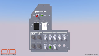
Flight Simulator Interface Panel 3D Render


These are 3D rendered images of my circuit breaker panel. There are obviously a number of differences from what is found in the real aircraft which I had to change to be a bit more practical for my simulator. Firstly, the real aircraft features a key lock starter switch with 5 positions. The positions are OFF, RIGHT, LEFT, BOTH and START. You can buy a similar starter from Simkits (www.simkits.com) but it turned out to be an expensive option. I decided to go for a similar system featured in my flight panel project (see my other blog for details on that) with the magnetos tied up to LEFT and RIGHT via toggle switches and push button START switch as used in some other Lycoming aircraft such as the American Champion Decathlon. OK it's not exactly that realistic but I decided against intergrating an expensive Simkits switch because of costs. The panel clearance is also thinner than the material I am using as well so it was a bit of a no brainer. It looks good and it's simple to operate as well!

I didn't have any way of replicating the circuit breakers like the type found in the real aircraft and I initially planned to make the panel the sama as the real one except with dummy push button switches that look like breakers. But it seemed such a waste to have so many buttons that could be used to operate the controls of FSX within the simulator rather then relying on a keyboard. So I began to work out which buttons I used the most and then started designing a flight simulator interface panel that wouldn't look out of place inside the cockpit. I left the fuse amp letting on the buttons to keep up the apperance of a circuit breaker panel. I put all of the slew mode buttons on the right hand side, with the familiar numpad setup of keyboard so they could be operated. Slew mode is a great way to re-position the aircraft to practice circuits or re-position the approach, so I think they will come in handy. The left side has a few various switches linked to relevant flight simulator interface commands such as pause and controls on/off. I also put in auto-start, auto-shutdown and all lights on/off just in case I am feeling lazy!

With this design of this panel I shifted the material from using 4mm aluminium (or a polycarbonate, I am not entirely sure yet, I am still a little worried about the weight of the switches and instruments as i found out in my previous project - one of the panels is very heavy) to go to 3mm instead. This is primarily because the push buttons replicating the breakers are manufactured to 3mm. I found them on Farnell they look like a very good match and are relatively cheap to buy.

Introducing the Cessna Glass Cockpit Project

This is the first post and general introduction to my new flight simulator project.

The Cessna Glass Cockpit (CGC) simulator project is something I have been working on for a a number of months. The project is based on a Cessna Skyhawk 172SP, which is a four-seat, single engined light aircraft. This current 'S' model was introduced in 1998 and features a modern glass cockpit, which replaces the more conventional mechanical gauges and avionics of the 'R' model. The 172SP includes the Garmin 1000 suite of avionics as standard. It features two LCD panels and one communications panel that replicates the basic flight instruments, navigational equipment and engine monitoring instrumentation found in a typical general aviation aircraft.

The CGC project is currently in the design phase and is more advanced than my previous flight simulator which can be found here: http://www.cessnasim.blogspot.com. I am using a professional CAD program and some 3D modelling software to pre-produce all of the panels and mouldings of the cockpit. I am hoping to iron out most of the problems that I came accross in my previous simpit by spending more time with the design of the simulator and not leaving it till later to find that a piece doesn't fit the way it should.

The project uses 2 x 10.4inch LCD screens with a 800 x 600 resolution. They are usually found in laptops or in kiosks with a touch screen panel attached. They are driven by circuit boards from EarthLCD (www.earthlcd.com) these come complete with a menu controller and an inverter (I put it in polycarbonate box, I really don't want to touch that thing!) Project magenta's GAGC software (www.projectmagenta.com) is used to replicate the Garmin 1000. Simkits makes up the instruments for the standbys, I have canobolised these from my previous project. I will be using a few of Leo Bodnar's circuit boards for the input/output of the switches and rotary encoders.

Please check back here for more news.

Rhydian

Thursday 14 January 2010

A New Year - A New Project.


The perfect recipe for a flight simulator?

Take a bunch of laser cut panels, a couple of well made plastic instruments and a whole heap of badly cut MDF and what does it make??? without careful planning... not a great deal actually. This is what I have found out over the now almost 6 plus years since I started dabbling in 'simpit' building. Quite frankly launching head first into constructing a complex homebuilt flight simulator is a recipe for disaster! If anybody starting out wants some advice before making their first project, it could be summed up in just three simple words! PLAN, MONEY and TIME! I am certain this is echoed all over the forums at Mycockpit.org and flightdecksolutions.com and not just by myself. Overlook all three and you could have a bit of a mess on your hands and it's the first one that has caused me the most pain, that I simply could have avoided if I had been more thoughtful. I managed to jump head first into making my first 'simpit' without doing enough planning and design work. Constructed out of 4mm laser cut aluminum panels and using Simkit's instruments, I still managed to make a respectable rendition (In my eyes at least) of a Cessna 172 cockpit. But it's when I started getting deeper into the project that things began to go wrong. Cutting my own MDF was a great, cheap alternative, but it was very time consuming and with my poor jigsawing, it led to some rather poor results that I wasn't particularly proud of. I left some of the complex parts like the yoke and throttle till later in the building process and came woefully unstuck. I believed that I could simply add it when I was further along... boy was I wrong on that one. So... this time around, and trust me, starting again hasn't been an easy decision, I am going to spend more time